This is your opportunity to practice the electrical diagnostic methods that this book has described. |
| A series of simulated faults have been created and you must use the test meter to diagnose and report the fault in each case. You must determine the fault from the meter readings since no other visual clues are provided on the schematics. Refer to the equipment nameplate just below the schematic for information such as rated voltage and rated RLA and LRA. AFTER you have determined the problem, submit your diagnosis in the chart at the bottom of the page to see if you are correct. |
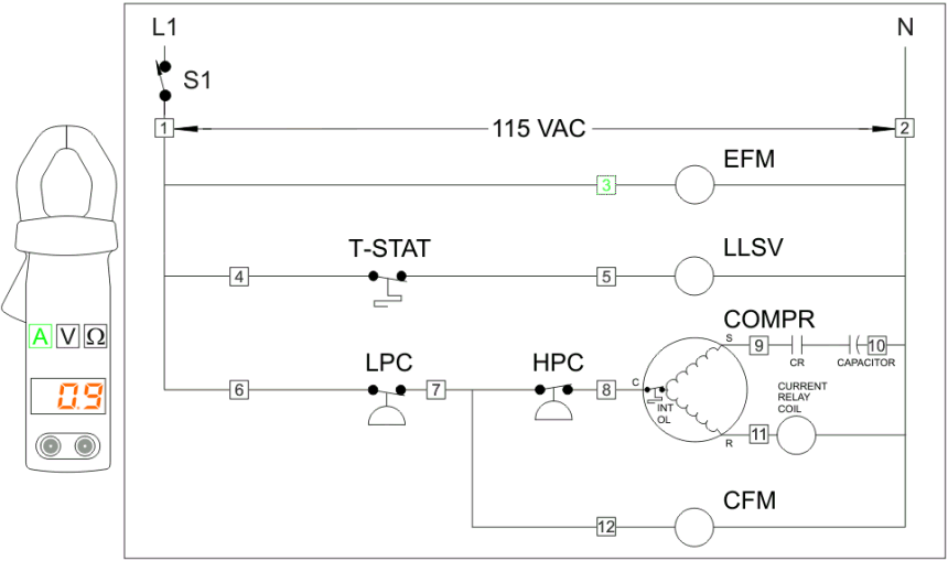
| To measure amperage, first you must put the meter into amperage mode by clicking the "A" button on the meter. Then click on any test point on the schematic. The amperage at that point will be displayed in the meter. The example above shows that the EFM is drawing 0.9 amps. |
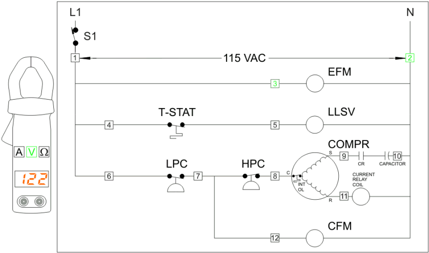
| To measure voltage, first you must put the meter into voltage mode by clicking the "V" button on the meter. Notice that the number 2 test point on the schematic automatically turns green indicating that it is selected. You require 2 test points to measure voltage potential between them and the number 2 test point (which is Neutral) is the appropriate place for one of the test leads. You must select any other test point and the voltage between the 2 points will be displayed in the meter. The example above displays that there is a 122 VAC potential between test point 2 and test point 3. In other words there is proper voltage to the EFM. If this is unclear review hop scotch troubleshooting techniques |

To measure ohms, first you must put the meter into ohms mode by clicking the  button on the meter. Then click on any 2 test points on the schematic. The resistance between those 2 points will
be displayed in the meter. The example above shows that the resistance between test points 2 and 3 is 15 ohms. In other words the resistance of the EFM windings is 15 ohms. You would realize from this measurement that
since the windings have a MR (Measureable Resistance) they are not burnt open. As to whether or not the EFM is seized, that would take an amperage reading or a physical inspection. button on the meter. Then click on any 2 test points on the schematic. The resistance between those 2 points will
be displayed in the meter. The example above shows that the resistance between test points 2 and 3 is 15 ohms. In other words the resistance of the EFM windings is 15 ohms. You would realize from this measurement that
since the windings have a MR (Measureable Resistance) they are not burnt open. As to whether or not the EFM is seized, that would take an amperage reading or a physical inspection. |
| Note: It is assumed that the power to the equipment is off when ever you place the meter in ohms mode. If you try to measure the resistance of a live circuit the fuse in the ohmeter will blow. It is further assumed
that the component being measured has been isolated from the rest of the circuitry to elimimate unwanted parallel and series loads (resistances). If you wish to measure the resistance of a component just select the two closest
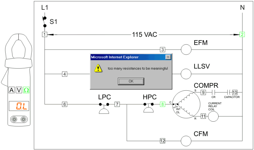
test points. Otherwise, if you select points with many resistances between them you will be alerted that there are too many resistances to be meaningful.
On the other hand, if there is a direct circuit between 2 ohmeter test points then any parallel resistance loads that exist will become a non issue. This is because electricity always takes the route of least resistance. So sometimes the meter will display 0 ohms between 2 test points that are far apart because a closed circuit with no loads connects them. Or, if there is only a single load between 2 test points, even if they are far from each other, the measureable resistance will be reported. With a real meter, the actual resistance of a complicated circuit with many parallel and/or series resistances would be displayed. Since that type of data is unlikely to be of any value when troubleshooting, the virtual meter has been programmed to display an alert message under those circumstances rather than confuse the issue. |
|